DC Relay with Wiring Harness Install Guide
Contents
- Quick Installation Summary
- Summary of Key Installation Steps
- Power Connections
- Fuse Selection
- Switch Cable
- Control via Relay-Based Control Panels
- Installation Notes
- Warning Summary / Safety Notice
- Warranty
Quick Installation Summary
The DC Relay with Wiring Harness is designed to provide reliable switched DC power for Starlink installations while keeping the high-current 12V or 24V cable run short.
Summary of Key Installation
- Mount the PSU close to the battery or fuse panel.
- Connect POWER IN to a protected DC supply.
- Connect the relay output cable to the PSU input.
- Fit the correct fuse:
- 7.5A MINI
- 15A Standard
- 25A Standard with router
- Ensure battery-side fuse protection is present.
- Wire the switch:
- red = control feed
- green = trigger
- black = LED negative only
- Route and secure cables properly.
- Check polarity, terminals and fuse selection before power-up.
- Test relay function before finalising the install.
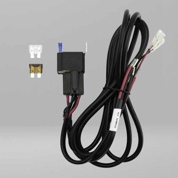
Power Connections
The harness includes two 2.5mm² two-core power cables:
- POWER IN - connect to the DC power source, battery or fuse panel
- Output cable - connect to the input of the selected PSU or DC2DC converter
Always confirm correct polarity before applying power.
Best Practice
Keep the low-voltage input side short and place the longer cable run on the higher voltage Starlink side wherever possible. This helps reduce voltage drop and improves reliable operation.
Fuse Selection
Fit the correct supplied fuse for the connected system:
- 7.5A - Starlink MINI
- 15A - Standard Starlink
- 25A - Standard Starlink with router
The relay harness includes an onboard fuse holder for load protection. The incoming supply should also be protected by a suitable upstream fuse or fuse block, ideally close to the battery.
Switch Cable
The 3-core switch cable controls relay operation:
- Red - control power in
- Green - relay trigger
- Black - negative for optional switch LED only
The relay engages when the red wire is connected to the green wire through a switch or control output.
If using the Starvmount illuminated switch:
- Middle silver pin - green
- Remaining silver pin - red
- Gold pin - black
WARNING: The black wire must only be used for the switch LED negative. Never connect the black wire directly to the red positive or across the switch contacts, as this will create a short circuit and may damage the harness.
Control via Relay-Based Control Panels
The DC Relay with Wiring Harness can be controlled by a relay-based control panel such as Victron Cerbo, Savvy Van, Eberspacher Zeliox or Garmin control panel.
In this type of installation, the control panel does not switch the Starlink power feed directly. Instead, it switches the relay trigger circuit on the DC Relay with Wiring Harness.
We use the DC Relay with Wiring Harness rather than switching Starlink directly via the control panel relay for two reasons:
- The Starlink power draw on the low voltage side peaks too high for most relay-based control panels, risking damage to expensive control panels.
- Routing the low voltage side of the Starlink circuit via the control panel would often require a longer cable run. Longer low voltage runs are more susceptible to voltage drop and may require heavier gauge cable, which can make physical termination more difficult. Together, these factors can result in unreliable Starlink operation.
For control panel use, connect the red and green wires from the 3-core switch cable to the control panel relay terminals. The black wire is not required in this use case and must not be connected.
When the control panel closes the circuit between red and green, the Wiring Harness DC Relay engages and supplies power to the connected PSU or Starlink power device.
This approach allows the control panel to provide convenient remote switching while the DC Relay with Wiring Harness handles the higher current low voltage switching locally, close to the battery or fuse panel.
Installation Notes
- Use only with 12V or 24V DC systems
- Do not connect directly to mains electricity
- Route cables away from heat, sharp edges and moving parts
- Secure all wiring against vibration and movement
- Do not use damaged cables, connectors or fuse holders
- Installation should be carried out by a competent person familiar with low-voltage DC systems
Warning Summary / Safety Notice
Use only with low voltage DC systems. Intended for 12V or 24V DC system switching applications. Maximum rated voltage: 48V DC. Do not connect directly to mains electricity.
Ensure correct polarity, suitable fuse protection and compatibility with the connected PSU and system current draw before use. Incorrect installation may cause short circuit, overheating or fire risk.
Check cable routing before installation. Avoid chafing, crushing, heat sources, water ingress, vibration and movement.
Do not use if the cable, connectors or insulation are damaged.
Installation should be carried out by a competent person familiar with low voltage DC systems.